Attention
This documentation is a work in progress. Expect to see errors and unfinished things.
cic_multichannel
Description
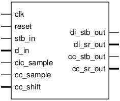
Pinout

Parameters
Name |
Min |
Max |
Default |
Description |
|---|---|---|---|---|
n_chan |
? |
? |
12 |
|
di_dwi |
? |
? |
16 |
data width |
di_rwi |
? |
? |
32 |
result width |
di_noise_bits |
? |
? |
4 |
Number of noise bits to discard at the output of Double Integrator. |
shift_delay |
? |
? |
0 |
Optional shifter between Integrator and Comb. A value of 0 disables shifter |
cc_outw |
? |
? |
20 |
CCFilt output width; Must be 20 if using half-band filter |
cc_halfband |
? |
? |
1 |
|
cc_use_delay |
? |
? |
0 |
Match pipeline length of filt_halfband=1 |
cc_shift_base |
? |
? |
0 |
Bits to discard from previous acc step |
cc_shift_wi |
? |
? |
4 |
Ports
Signal |
Direction |
Description |
|---|---|---|
clk |
Input |
|
reset |
Input |
|
stb_in |
Input |
Strobe signal for input samples |
d_in[n_chan*di_dwi-1:0] |
Input |
Flattened array of unprocessed data streams. CH0 in LSBs |
cic_sample |
Input |
CIC base sampling signal |
cc_sample |
Input |
CCFilt sampling signal |
cc_shift[cc_shift_wi-1:0] |
Input |
controls scaling of filter result |
di_stb_out |
Output |
|
di_sr_out[di_rwi-1:0] |
Output |
|
cc_stb_out |
Output |
|
cc_sr_out[cc_outw-1:0] |
Output |
Implementation and use
The portable Verilog implementation can be found in cic_multichannel Source File
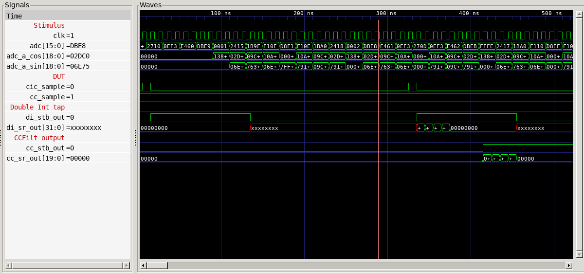
Timing Diagram
A GTKWave-generated timing diagram is shown below:
