Attention
This documentation is a work in progress. Expect to see errors and unfinished things.
upconv
Description
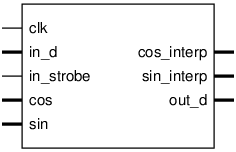
Pinout

Ports
Signal |
Direction |
Description |
|---|---|---|
clk |
Input |
|
in_d[15:0] |
Input |
baseband, interleaved I and Q |
in_strobe |
Input |
Set at I time, Q follows |
cos[15:0] |
Input |
LO input |
sin[15:0] |
Input |
LO input |
cos_interp[15:0] |
Output |
interpolated output immediately before upconversion |
sin_interp[15:0] |
Output |
|
out_d[15:0] |
Output |
at IF |
Implementation and use
The portable Verilog implementation can be found in upconv Source File
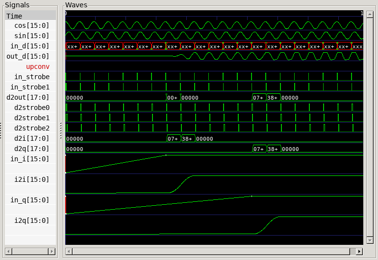
Timing Diagram
A GTKWave-generated timing diagram is shown below:
