Attention
This documentation is a work in progress. Expect to see errors and unfinished things.
multi_counter
Description
Single-clock-domain multi-channel counter
No restrictions on how often the “inc” port is high.
Reads go through dpram, so are delayed one cycle.
Reads are passive, so don’t need an enable.
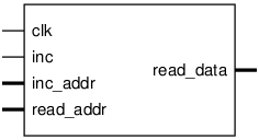
Pinout

Parameters
Name |
Min |
Max |
Default |
Description |
|---|---|---|---|---|
aw |
? |
? |
4 |
2**aw counters, non-resettable |
dw |
? |
? |
16 |
bit-width of each counter |
Ports
Signal |
Direction |
Description |
|---|---|---|
clk |
Input |
|
inc |
Input |
increment the counter specified by inc_addr |
inc_addr[aw-1:0] |
Input |
|
read_addr[aw-1:0] |
Input |
local bus address |
read_data[dw-1:0] |
Output |
Implementation and use
The portable Verilog implementation can be found in multi_counter Source File
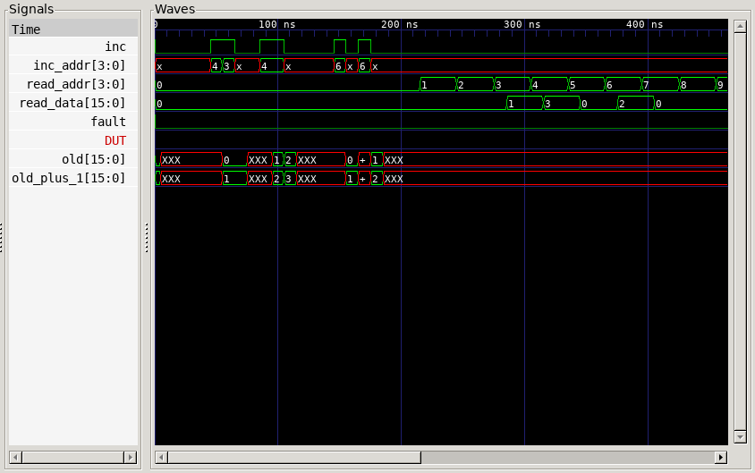
Timing Diagram
A GTKWave-generated timing diagram is shown below:
