Attention
This documentation is a work in progress. Expect to see errors and unfinished things.
iq_trace
Description
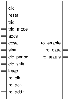
Pinout

Parameters
Name |
Min |
Max |
Default |
Description |
|---|---|---|---|---|
dw |
? |
? |
16 |
ADC input width |
oscw |
? |
? |
18 |
Oscillator input width |
davr |
? |
? |
3 |
Guard bits at output of mixer |
ow |
? |
? |
28 |
second-order CIC data path width |
rw |
? |
? |
20 |
result width out of ccfilt |
pcw |
? |
? |
13 |
cic_period counter width |
shift_base |
? |
? |
7 |
see ccfilt.v |
nadc |
? |
? |
8 |
|
aw |
? |
? |
13 |
for circle_buf, see below |
Ports
Signal |
Direction |
Description |
|---|---|---|
clk |
Input |
|
reset |
Input |
|
trig |
Input |
|
trig_mode[1:0] |
Input |
0: free-run, 1: single-shot, 2: sync start, XXX not yet used |
adcs[nadc*dw-1:0] |
Input |
each dw-wide adc data is signed |
cosa[oscw-1:0] |
Input |
|
sina[oscw-1:0] |
Input |
|
cic_period[pcw-1:0] |
Input |
expected values 33 to 33*128 |
cic_shift[3:0] |
Input |
expected values 7 to 15 |
keep[nadc-1:0] |
Input |
bit n :: channel n |
ro_clk |
Input |
|
ro_enable |
Output |
|
ro_ack |
Input |
|
ro_addr[aw+1:0] |
Input |
|
ro_data[31:0] |
Output |
|
ro_status[31:0] |
Output |
Implementation and use
The portable Verilog implementation can be found in iq_trace Source File
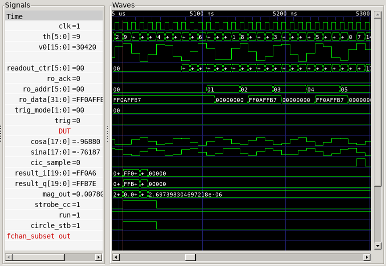
Timing Diagram
A GTKWave-generated timing diagram is shown below:
