Attention
This documentation is a work in progress. Expect to see errors and unfinished things.
circle_buf
Description
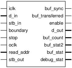
Pinout

Parameters
Name |
Min |
Max |
Default |
Description |
|---|---|---|---|---|
dw |
? |
? |
16 |
|
aw |
? |
? |
13 |
|
stat_w |
? |
? |
16 |
Width of buffer statistics |
auto_flip |
? |
? |
1 |
Ports
Signal |
Direction |
Description |
|---|---|---|
iclk |
Input |
|
d_in[dw-1:0] |
Input |
|
stb_in |
Input |
d_in is valid |
boundary |
Input |
between blocks of input strobes |
stop |
Input |
single-cycle |
buf_sync |
Output |
single-cycle when buffer starts/ends |
buf_transferred |
Output |
single-cycle when a buffer has been |
oclk |
Input |
|
enable |
Output |
|
read_addr[aw-1:0] |
Input |
nominally 8192 locations |
d_out[dw-1:0] |
Output |
|
stb_out |
Input |
|
buf_count[stat_w-1:0] |
Output |
number of full buffer writes |
buf_stat2[aw-1:0] |
Output |
last valid location |
buf_stat[stat_w-1:0] |
Output |
includes fault bit, and (if set) the last valid location |
debug_stat[aw+4:0] |
Output |
{stb_in, boundary, btest, wbank, rbank, wr_addr} |
Implementation and use
The portable Verilog implementation can be found in circle_buf Source File
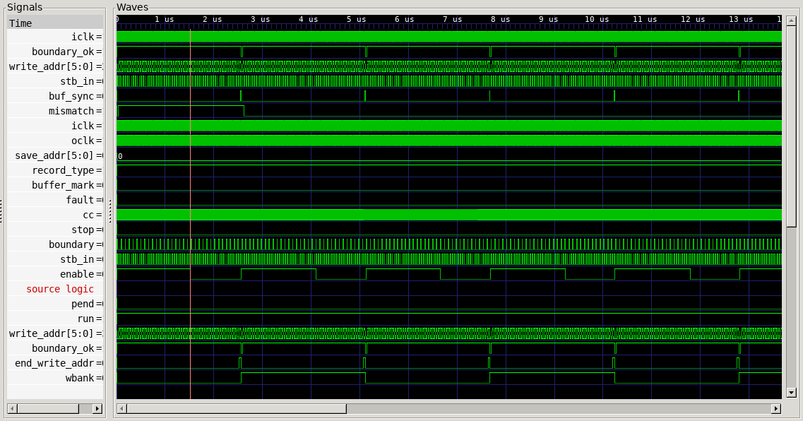
Timing Diagram
A GTKWave-generated timing diagram is shown below:
