Attention
This documentation is a work in progress. Expect to see errors and unfinished things.
phaset
Description
Digital phase-locked-loop tracker
At least in this application, the sampling clock is not phase-locked
to the clocks of interest. So a binary phase accumulator is as good
as any, and it makes the arithmetic for subtracting the two results
(from the two unknown clocks) easy.
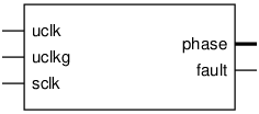
Pinout

Parameters
Name |
Min |
Max |
Default |
Description |
|---|---|---|---|---|
order |
? |
? |
1 |
|
dw |
? |
? |
14 |
|
delta |
? |
? |
16 |
Ports
Signal |
Direction |
Description |
|---|---|---|
uclk |
Input |
|
uclkg |
Input |
|
sclk |
Input |
|
adv[dw-1:0] |
Input |
|
phase[dw-1:0] |
Output |
|
fault |
Output |
single cycle |
Implementation and use
The portable Verilog implementation can be found in phaset Source File
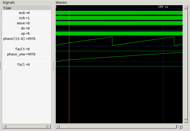
Timing Diagram
A GTKWave-generated timing diagram is shown below:
