Attention
This documentation is a work in progress. Expect to see errors and unfinished things.
biquad
Description
Biquad IIR filter
y(t) = u(t)*b0 + u(t-1)*b1 + u(t-2)*b2 + y(t-1)*(-a1) + y(t-2)*(-a2)
Minimizes latency by computing all but u(t)*b0 at end of previous sample.
Minimizes resource consumption by using internal
DSP registers for between-sample storage.
Writing a coefficient holds the filter in reset until address 7 is written.
This allows usage of a consistent set of coefficients.
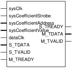
Pinout

Parameters
Name |
Min |
Max |
Default |
Description |
|---|---|---|---|---|
DATA_WIDTH |
? |
? |
28 |
|
DATA_COUNT |
? |
? |
1 |
|
COEFFICIENT_WIDTH |
? |
? |
25 |
|
DEBUG |
? |
? |
Ports
Signal |
Direction |
Description |
|---|---|---|
sysClk |
Input |
|
sysCoefficientStrobe |
Input |
|
sysCoefficientAddress[2:0] |
Input |
|
sysCoefficientValue[COEFFICIENT_WIDTH-1:0] |
Input |
|
dataClk |
Input |
|
S_TDATA[(DATA_COUNT*DATA_WIDTH)-1:0] |
Input |
|
S_TVALID |
Input |
|
S_TREADY |
Output |
|
M_TDATA[(DATA_COUNT*DATA_WIDTH)-1:0] |
Output |
|
M_TVALID |
Output |
|
M_TREADY |
Input |
Implementation and use
The portable Verilog implementation can be found in biquad Source File
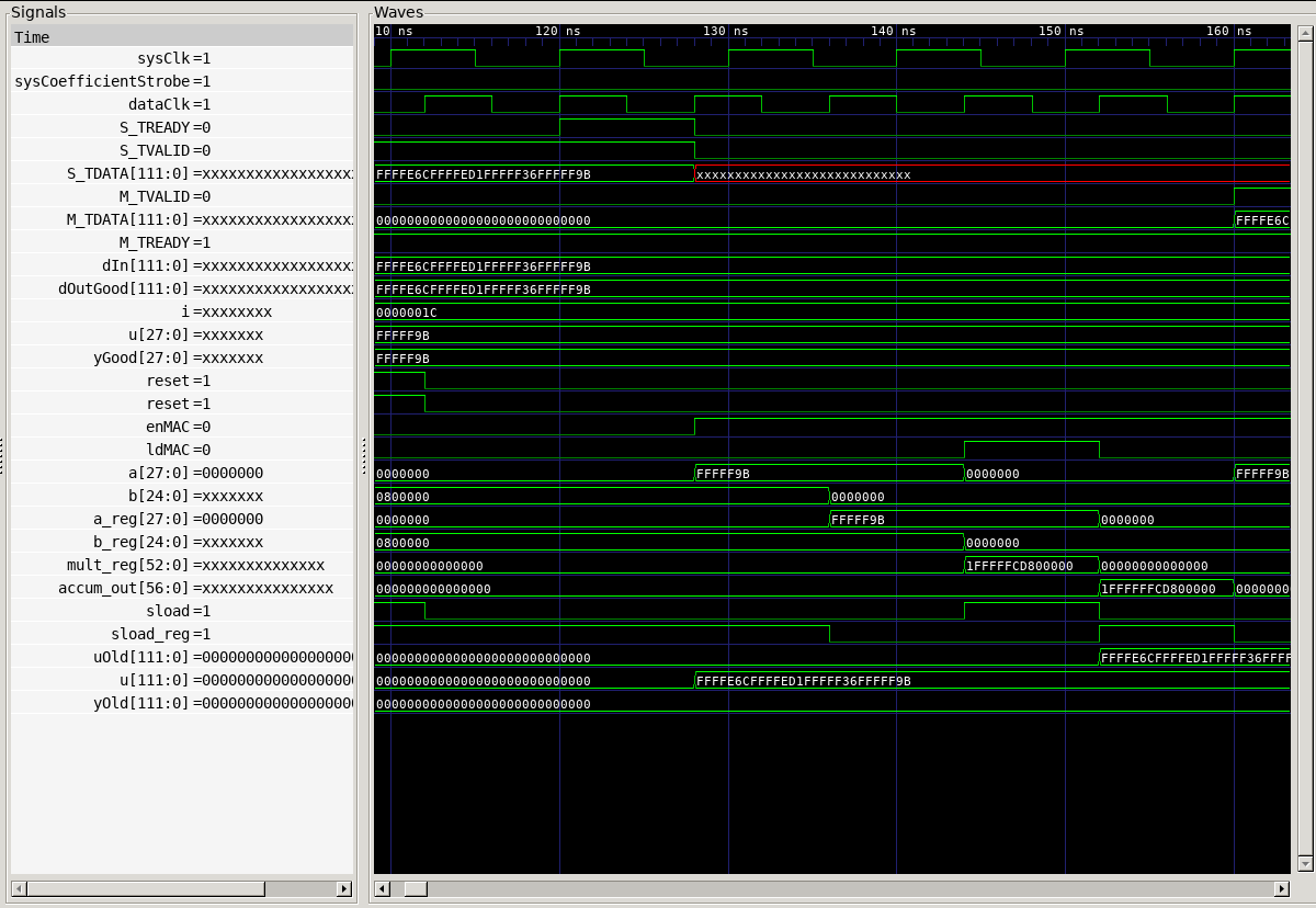
Timing Diagram
A GTKWave-generated timing diagram is shown below:
