Attention
This documentation is a work in progress. Expect to see errors and unfinished things.
timestamp
Description
High-speed cycle counter
This module attaches to the slow readout bus used in many
LBNL DAQ builds. It provides a 59-bit cycle counter (since chip boot),
and an optional timestamp capture register.
The 8-bit-wide shift-register-style output is ready to be merged
in a “slow” DSP data stream, LSB-first. Sorry about the byte-order,
but it’s intrinsic to the mechanism used.
Synthesizes to 54 LUTs and 31 Flip flops at 150 MHz in XC3S1000-5 with XST 12.1 (aux_reg=0)
Synthesizes to 101 LUTs and 65 Flip flops at 150 MHz in XC3S1000-5 with XST 12.1 (aux_reg=1)
59-bit counter will wrap every 182 years if clocked at 100 MHz.
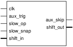
Pinout

Parameters
Name |
Min |
Max |
Default |
Description |
|---|---|---|---|---|
dw |
? |
? |
8 |
|
aux_reg |
? |
? |
0 |
Ports
Signal |
Direction |
Description |
|---|---|---|
clk |
Input |
timespec 6.6 ns |
aux_trig |
Input |
|
aux_skip |
Output |
|
slow_op |
Input |
|
slow_snap |
Input |
|
shift_in[7:0] |
Input |
|
shift_out[7:0] |
Output |
Implementation and use
The portable Verilog implementation can be found in timestamp Source File
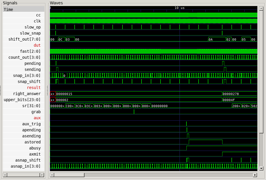
Timing Diagram
A GTKWave-generated timing diagram is shown below:
