Attention
This documentation is a work in progress. Expect to see errors and unfinished things.
half_filt
Description
Multiplier-free half-band filter and decimator.
This is an FIR filter
with 7 non-zero taps, categorized as an order-3 half-band filter.
The taps are
2 0 -9 0 39 64 39 0 -9 0 2
The filter has a nominal low-frequency gain of unity. But since
the gain peaks at +0.074 dB (at an input frequency of 0.12 of the input
sample rate), the output can clip. The module correctly saturates
its arithmetic.
This filter is linear-phase (note the symmetric tap coefficients),
with an essential DSP group delay of 5 samples.
Additional pipeline delay is added by the implementation; see below.
The input can consist of a fixed (set by the parameter len at
build-time) number of interleaved signal data streams.
The half-band filter is applied to each stream independently.
half_filt() can accept 20-bit data at the full clock rate.
The output stream is decimated by two; blocks of len cycles of 20-bit
output data are interleaved with len silent cycles. The input data
and ing control are pipelined four cycles before getting to the output.
There are no restrictions on the ing pattern. The len-way
interleaving of the input data ignores cycles with ing low.
Synthesizes to 251 slices at 116 MHz in XC3Sxxx-4 using XST-8.2i
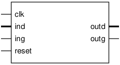
Pinout

Parameters
Name |
Min |
Max |
Default |
Description |
|---|---|---|---|---|
len |
? |
? |
4 |
number of interleaved data streams |
Ports
Signal |
Direction |
Description |
|---|---|---|
clk |
Input |
Rising edge clock input; all logic is synchronous in this domain |
ind[19:0] |
Input |
Input data |
ing |
Input |
Active high gate marking input data as valid |
outd[19:0] |
Output |
Output data |
outg |
Output |
Active high gate marking output data as valid |
reset |
Input |
manually reset counter |
Implementation and use
The portable Verilog implementation can be found in half_filt Source File
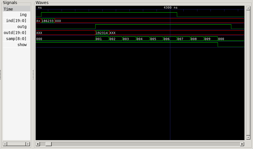
Timing Diagram
A GTKWave-generated timing diagram is shown below:
